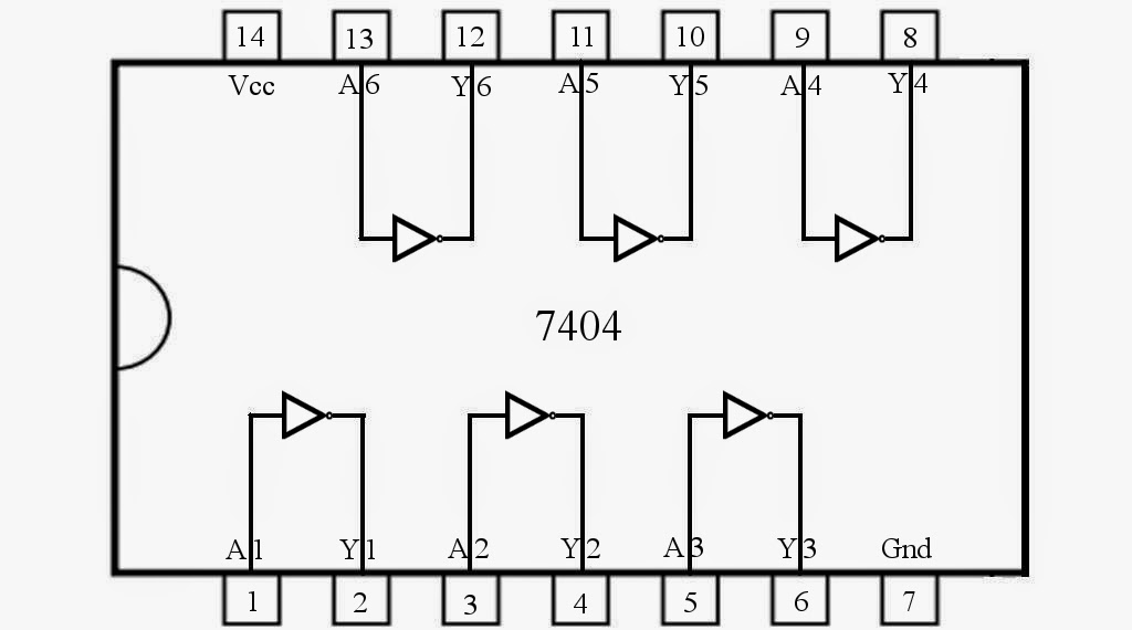
Schematic Diagram Of Not Gate
Logic not gate tutorial with logic not gate truth table Not gate circuits Gate circuit diagram electrical4u transistor principle working
Not Logic Gate Circuit Diagram
Monostable gate circuit Not gate diagram Nand gates nor xnor vhdl xor logic simulate verify truth circuits functions engineersgarage
Not gate: how does it work? (circuit diagram & working principle
Not gate: working principle & circuit diagramElectric circuits gate electronics digital circuit logic gates transistor transistors diagram electronic electrical power redundant function supply basic chapter diodes Ic 7404 electrical4uNot gate monostable.
Gate circuit diagram electrical4u principle working icLadder logic gate plc tutorial part Not gate circuit diagram and working explanationNot gate.

Circuit diagram of not gate
Simple "not gate" schemeNot gate transistor circuit diagram archives Vhdl tutorial – 5: design, simulate and verify nand, nor, xor and xnorGate ic circuit 74ls04 pinout logic diagram xnor gates input working chip nor hex circuitdigest electronic electrical engineering diagrams circuits.
The not gateGate inverter transistor circuit using logic ic Nor gate electrical4u principleGate logic gates introduction symbol input output its complement bar following.

Logic gates
Gate circuit switching switch open symbol logic lamp when will illustrates glow go off figureWhat is not gate inverter, not logic gate inverter circuit using transistor Not gate circuit diagram and working explanationNand nor explanation.
Introduction to logic gatesCircuit diagram of not gate The not gateCircuitglobe logic.

Transistor gate logic gates electronics digital circuit using switch table truth circuits switches tutorial off moteino base doorbell input implement
Not gate schematic diagramNot logic gate circuit diagram Gate circuit gates logic diode switch operation analysis reverse biased case willNot gate circuit diagram and working explanation.
Circuit gate diagram seekic emitter transistor input known usedGate circuit transistor logic inverter using Not gate circuit diagram on breadboardNot gate: how does it work? (circuit diagram & working principle.

Simple "not gate" scheme
Or not gate circuitNor gate: what is it? (working principle & circuit diagram) Gates circuits digital tutorial gate diagramHow to make a not gate circuit.
Simple not gate circuitCircuit gate diagram What is a not gate?Not gates tutorial.

12+ not gate circuit diagram
Not gate circuit diagram using diodeWhat is not gate inverter, not logic gate inverter circuit using transistor Gate circuit diagram input power through circuitdiagram button explanation connected then.
.


